
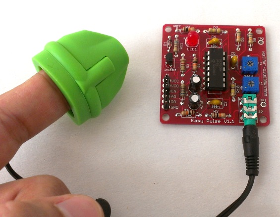
Easy Pulse Sensor Version 11 Overview Part 1 Circuit Diagram How the Circuit Works. Any one of the total four gates can be used to produce an oscillator with a variable duty-cycle and a set frequency. The RC time-constant of this network that has a capacitor C1 and resistor R1+P1 helps in determining the pulse duration.
How to make a Simple Heartbeat Sensor Circuit. 19654 Views May 19, 2019 Afzal Rehmani . Electronics Projects LM358 Circuits Simple Electronic Circuits. The Heartbeat Sensor is used to measure the functions of the heart like heart rate (speed of the heart) body temperature & blood pressure. Today, Heartbeat Sensors are not only used in medical
DIY Arduino Pulse Sensor : 10 Steps Circuit Diagram
This current is called the reflected pulse and is extremely short, lasting only about 30 microseconds. Another pulse is then sent and the process repeats. If a piece of metal comes inside the range of the magnetic field lines, the receive coil can detect a change in both amplitude and phase of the received signal.
One solution would be to add more inverters to your pulse generator. Another would be to use a differential detector with a lower threshold and higher input impedence. You need to create a specification for your circuit. E.g., what are the static timing characteristics of the pulse you want to detect?
Rising edge pulse detector from logic gates Circuit Diagram
The high pass filter created by the 1k resistor and 10uF capacitor (Step 7) is not very well tuned for the pulse frequency. The cut-off frequency for the 1k resistor and 10uF capacitor is about 16Hz which is well above the pulse frequency of 1.2Hz. Unfortunately, I simply overlooked this when first making the circuit. In this video, I'm gonna show you how to make a simple pulse oximeter at home by doing it yourself. This device will read SpO2 and Heart data from the MAX30100 sensor and display it on the OLED Display. I'm gonna use a conventional pulse oximeter-like device for this project, which I made in one of my previous videos.